AGV Drive Engineering

AGV Navigation Methods Compared: Magnetic Tape, QR Code, Laser & SLAM — and What Each Means for the Drive Motor

Short answer: industrial AGVs navigate in four main ways — magnetic tape (or buried wire) line following, QR code floor grids, laser triangulation off wall reflectors, and natural-feature SLAM with LiDAR. Tape and QR are cheap and predictable but fix the route in the floor; laser and SLAM move the route into software. What most comparisons leave out is that the navigation method also decides what the AGV drive motor has to do: how much it must rely on its own feedback between position fixes, how slowly it must creep into a station, and whether a Hall-sensor driver is enough or a closed-loop encoder drive is needed.

Key takeaways for drive-system engineers

  • The fewer position fixes per metre, the more the drive wheel becomes the sensor. Tape corrects continuously; QR grids and SLAM rely on wheel odometry between fixes.
  • Through a gearbox, Hall feedback is finer than it looks — about 0.9 mm of travel per Hall edge in the worked example below. The real limit is how few edges arrive per second at docking speed.
  • Tape and QR fleets commonly run on sensored square-wave drivers such as our 48V dual-motor AGV drivers. SLAM and precision docking point toward an incremental encoder plus a closed-loop servo drive.
  • Navigation does not set motor power. Payload, gradient and speed do — the navigation method shapes feedback, gear ratio and brake choices.
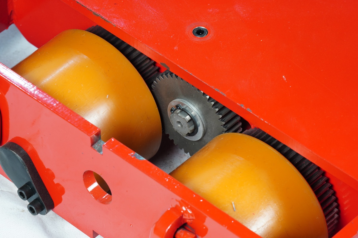
Polyurethane AGV drive wheels with spur gear on a Shenghe heavy-load transfer cart chassis
The drive wheel is both actuator and, between navigation fixes, the vehicle’s position sensor. Shown: polyurethane drive wheels on a Shenghe heavy-load transfer cart.

How Do AGVs Work? Navigation, Then Motion

Every AGV runs the same loop. The navigation system answers “where am I and where should I be?”; the vehicle controller turns that error into left/right wheel speed commands; and the drive system — BLDC motor, gearbox and motor driver — turns those commands into wheel motion. On a differential-drive AGV, steering is simply a speed difference between two drive wheels, so the drive motors execute every correction the navigation system makes.

Between position fixes, the controller estimates movement from wheel rotation (odometry). How often fixes arrive — continuously, once per grid cell, or once per laser scan — is the single biggest difference between navigation methods from the drive motor’s point of view.

Low-profile warehouse AGV with differential drive wheels and front safety scanner
A low-profile warehouse AGV: two drive wheels steer by speed difference, so every navigation correction becomes a motor speed command.

AGV Navigation Methods at a Glance

MethodHow position is foundFloor / site workRoute changesWhat it asks of the drive motor
Magnetic tape / wireSensor reads tape continuously; RFID or magnetic markers at stopsTape on (or wire in) every routeRe-lay tapeStable speed loop; Hall feedback often enough
QR code / floor tagsDownward camera reads a code at each grid cellCodes on a gridAdd / move codesAccurate odometry between codes; matched wheel speeds; in-place rotation
Laser reflectorRotating laser triangulates off wall reflectorsReflectors on walls / racksSoftware, if reflectors stay visibleSmooth low-speed control for docking
Natural-feature SLAMLiDAR scans matched to a map of the buildingNone (mapping run)SoftwareHigh-rate wheel odometry; encoder and closed-loop drive recommended

The Number Most Comparisons Skip: Feedback Counts per Millimetre at the Wheel

A BLDC motor with three Hall sensors produces 6 states per electrical revolution. Multiply by the motor’s pole pairs, then by the gear ratio, and you get the feedback counts per wheel revolution. Here is a worked example using our BL104 48V 1000W gear motor (3,000 rpm rated, ratios 30:1 to 100:1) on a 200 mm wheel. Pole count varies by motor — we assume an 8-pole (4 pole-pair) rotor for illustration; check the datasheet of the motor you actually specify.

Hall counts / wheel rev = 6 × pole pairs × gear ratio = 6 × 4 × 30 = 720
Travel per count = π × 200 mm / 720 ≈ 0.87 mm
Same motor with a 2,500 PPR encoder (×4 quadrature): 10,000 × 30 = 300,000 counts → ≈ 0.002 mm

So the gearbox already makes Hall feedback sub-millimetre at the wheel. Resolution is not what fails first. Update rate at low speed is. At a 50 mm/s docking creep, the Hall example produces only about 57 edges per second — a new position reading roughly every 17 ms — while the encoder version delivers more than 20,000 counts per second. A speed loop fed every 17 ms reacts late, and the vehicle surges and hesitates as it noses into a charger or conveyor transfer.

Also note what no encoder fixes: wheel slip, polyurethane tread wear and wheel-diameter tolerance. Those errors grow with distance, which is why every navigation method needs some external fix — the question is only how far the wheel has to carry the estimate in between.

Working out feedback for your AGV? Send wheel diameter, top speed, slowest docking speed and your navigation method — we will suggest a ratio and feedback option for the drive motor.

Request a drive-motor recommendation BLDC motor with encoder options

BL104 Ratio vs Wheel Speed (200 mm wheel)

RatioOutput rpmOutput torque*Travel speedHall travel / count**
30:1100≈ 76 N·m1.05 m/s0.87 mm
40:175≈ 102 N·m0.79 m/s0.65 mm
50:160≈ 127 N·m0.63 m/s0.52 mm
75:140≈ 191 N·m0.42 m/s0.35 mm
100:130≈ 254 N·m0.31 m/s0.26 mm

*Factory-rated output torque at ~80% gearbox efficiency, from the BL104 spec sheet. **Assumes 4 pole pairs, for illustration. Travel speed = output rpm × π × 0.2 m / 60.

A higher ratio gives more torque, finer feedback per millimetre and more motor rpm at creep speed — all useful for docking-heavy QR and SLAM vehicles — at the cost of top speed.

Magnetic Tape and Wire Guidance

How it works: a sensor bar under the vehicle reads a magnetic tape (or the field of a wire buried in the floor) and reports how far the vehicle is off-centre. Stops, junctions and speed zones are marked with RFID tags or magnetic spots. It is the lowest-cost, most predictable method and still common on tuggers, assembly-line carts and transfer carts.

Limits: the route is physically in the floor. Changing a layout means re-laying tape, and tape in forklift traffic wears and needs maintenance.

What it means for the drive motor: lateral error is corrected continuously, so the drive only has to follow speed commands smoothly and keep both wheels matched. Longitudinal position resets at every marker. This is the application where Hall-sensor feedback and a sensored square-wave driver are most often sufficient — our 48V-50A-D001 (1,500 W, one driver for two motors of 120–1,000 W) and 48V-45A-D003 (1,200 W) AGV drivers are built for exactly this dual-motor layout. Add an encoder if the vehicle must stop precisely between markers or creep into a station.

QR Code and Floor-Tag Grid Navigation

How it works: a downward camera reads a code at each cell of a floor grid, giving an absolute position and heading fix. Between codes the vehicle drives on odometry. This is the familiar goods-to-person layout: low-profile robots that drive under shelves and rotate on the spot.

Limits: codes get scuffed and dirty, and the vehicle must hit the next code’s field of view, so floor flatness and cleanliness matter.

What it means for the drive motor: the drive carries the position estimate across every grid cell, so wheel-to-wheel speed matching and repeatable odometry matter more than with tape — a small speed mismatch between left and right wheels becomes a heading error by the next code. In-place rotation under load also demands smooth torque at near-zero speed. For these vehicles we generally recommend an incremental encoder (1,024–2,500 PPR are the standard options on our encoder-equipped BLDC motors) and closed-loop speed control.

Laser (Reflector) Navigation

How it works: a rotating laser scanner on a mast measures angles to reflectors mounted on walls and racking and triangulates the vehicle’s position. Routes become virtual — changed in software as long as enough reflectors stay in view. It is widely used on automated forklifts and pallet movers that must place loads precisely.

Limits: reflectors must be installed and surveyed, and racking or stacked goods can block line of sight.

What it means for the drive motor: position fixes arrive at the scanner’s rate, so odometry only bridges short gaps. The demanding part is the final approach: forks entering a pallet or a cart docking to a conveyor at walking pace or slower. That puts the emphasis on smooth low-speed torque and fast speed feedback — see the update-rate example above — and, on heavy vehicles, on a brake that holds the load during transfer.

Natural-Feature Navigation (LiDAR SLAM)

How it works: the vehicle builds a map of walls, columns and fixed equipment, then localises by matching live LiDAR scans to that map (Simultaneous Localisation and Mapping). No floor or wall infrastructure is needed, which is why most AMRs use it. MHI describes natural-contour LiDAR as able to reach accuracy “below 10 mm” (MHI).

Limits: open, changing or featureless areas (long identical aisles, wide docks) can confuse scan matching, and setup needs more engineering effort.

What it means for the drive motor: wheel odometry is a direct input to the localisation filter, not just a stop-gap. Noisy or delayed wheel-speed data shows up as position jitter. SLAM vehicles are where we most strongly recommend an encoder on each drive motor and a closed-loop drive — for example a servo drive with FOC control such as the BLDB6010 listed on our AGV drive system reference page — reporting speed back to the navigation computer over CANopen or RS485.

Matching the Drive System to the Navigation Method

Use the table as a starting point. Motor power still comes from payload, gradient and speed — run the numbers with our AGV motor sizing guide first, then apply the navigation-driven choices on the right.

Shenghe BL80 48V 120W L-type BLDC gear motor for light AGV and AMR wheels
BL80 — 60–120 W, ratios up to 136:1
Shenghe BL90 48V 400W L-type BLDC gear motor with 20 mm hollow shaft
BL90 — 200–400 W, 30:1 / 40:1 / 100:1
Shenghe BL104 48V 1000W L-type BLDC gear motor for AGV traction
BL104 — 200–1,000 W, five ratios 30:1–100:1

When does the navigation method call for a brake?

A holding brake is needed when the AGV must hold position on a slope, stop within a defined distance on an emergency stop, or stay put during charging or load transfer. Laser-guided forklifts and heavy transfer carts almost always need one; flat-floor QR robots on short cycles often do not. Brake gearbox options are available on our larger frames — tell us the vehicle mass and gradient so holding torque can be confirmed in the quotation.

Navigation Method → Drive Configuration

NavigationFeedbackDriver typeGear ratio biasBrake
Magnetic tape / wireHall (encoder if stopping between markers)Sensored square-wave, dual-motor (e.g. D001, D003, D005)By top speedIf slopes or load transfer
QR code gridIncremental encoder 1,024–2,500 PPRClosed-loop speed controlHigher ratio for in-place rotation torqueUsually optional on flat floors
Laser reflectorIncremental encoderClosed-loop; smooth creepHigher ratio for dockingUsually required (forklift / heavy)
Natural-feature SLAMIncremental encoder, speed reported to nav computerServo / FOC drive (e.g. BLDB6010), CANopen or RS485Balanced: speed vs creepBy application

Typical gear motor by vehicle class: light AMR → BL80; 50–200 kg → BL90; 200–500 kg → BL104; heavy AGV and transfer carts → BL120 2000W right-angle (300 N·m at 100:1).

Shenghe BL120 48V 2000W right-angle BLDC gear motor for heavy AGV traction
BL120 48V 2000W right-angle gear motor, 30 mm hollow shaft — heavy AGV and transfer cart traction.

Choosing the Drive Motor for Your AGV?

Tell us payload, wheel diameter, top and docking speed, battery voltage, navigation method and the feedback your controller expects. Our engineers will suggest motor, gear ratio, feedback and driver from the BL80–BL120 range.

Request AGV Motor Quote WhatsApp
FAQ

AGV Navigation Methods: Frequently Asked Questions

Questions we hear from AGV builders and integrators when the navigation method is being chosen alongside the drive system.

What are the main AGV navigation methods?

Magnetic tape (or buried wire), QR code / floor-tag grids, laser navigation with wall reflectors, and natural-feature LiDAR SLAM. Tape and QR are fixed-path and low cost; laser and SLAM are virtual-path. Many fleets combine two, for example SLAM for travel and a marker or reflector for final docking.

Does a magnetic tape AGV need an encoder?

Often not. Tape gives continuous lateral correction and markers reset position at stops, so Hall feedback with a sensored square-wave driver is common. Add an encoder for slow, precise docking or long off-tape sections.

Which navigation method needs the best motor feedback?

SLAM and QR-grid navigation, because both rely on wheel odometry between fixes. An incremental encoder (typically 1,024–2,500 PPR) with closed-loop speed control is the usual choice. Laser sits in between; tape needs the least.

Does the navigation method change motor power?

Not directly. Power comes from mass, rolling resistance, gradient, acceleration and top speed. Navigation changes the feedback device, controller, gear ratio and sometimes the brake.

What should I send a motor supplier?

Payload and vehicle mass, wheel diameter, top and docking speed, gradient, drive layout, battery voltage, navigation method, the feedback interface your controller expects (Hall, A/B/Z, CANopen) and any holding-brake requirement. Send it here.